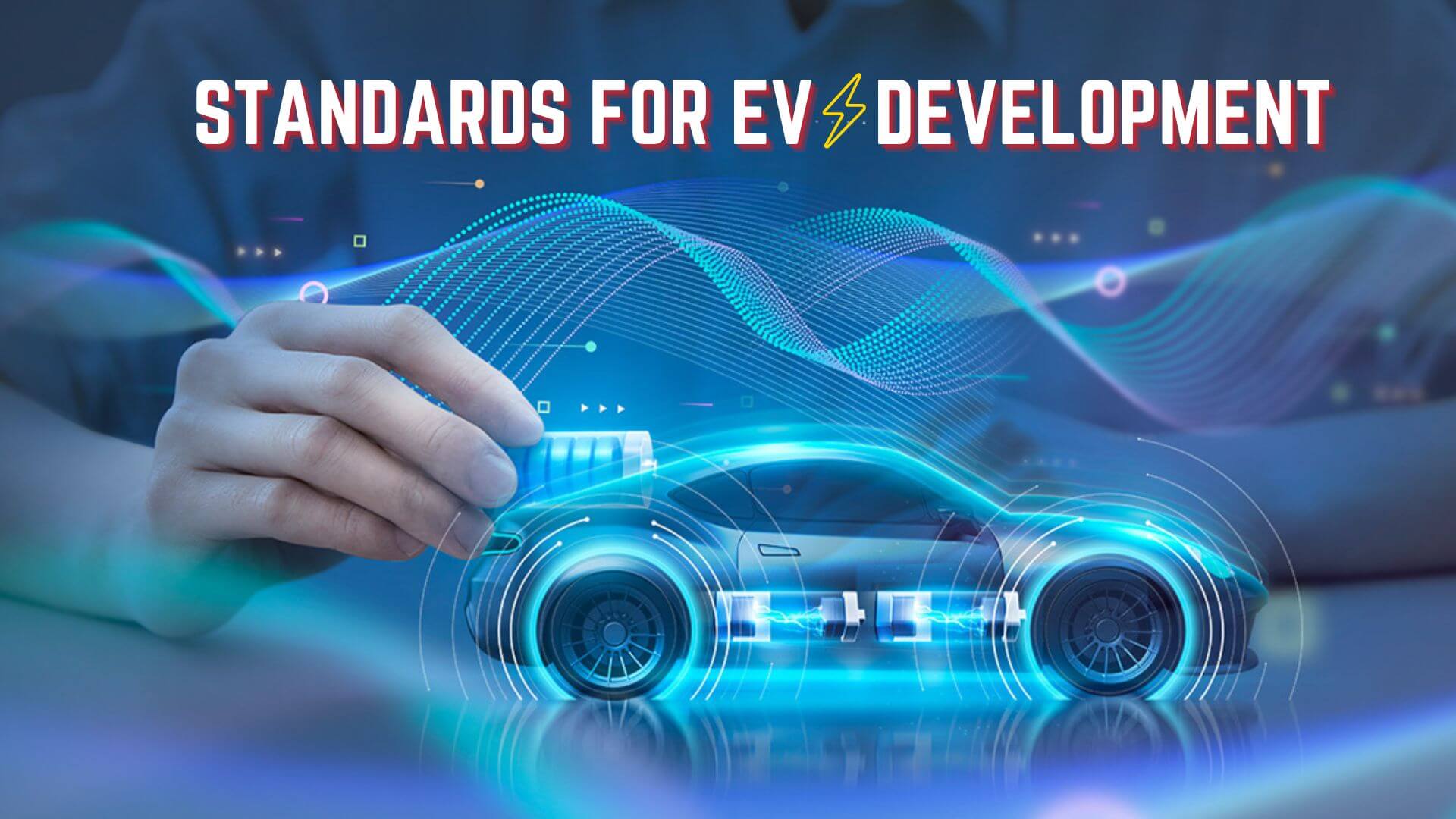
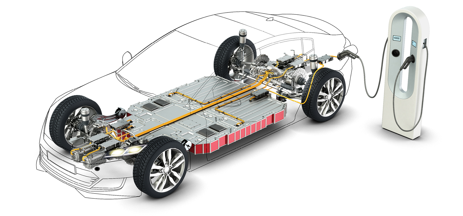
 Electric Powertrain contains three major components, the motor, converter, and battery. The other auxiliary components that make up the powertrain are battery and thermal management systems.
Table of Contents
Indian Standards for the Electric Vehicle Development
- AIS 039 – Energy Consumption
- AIS 040 – Measuring the range of the EV
- AIS 041 – Electric motor characterization
- Additional CMVR Rules
 AIS 039 – Energy consumption:
- This standard specifies the methods for measuring the electrical energy of the vehicle. The unit of measurement is Wh/km.
- It measures the min power and torque-speed characteristics of the motor alongside the analysis of torque.
- It measures the cold start performance, regenerative braking, thermal properties, and overload capacities.
Conditions for testing:
- The tires are inflated to the manufacturer’s specifications at ambient temperature with ambient, and the auxiliary lights are switched off. The energy storage systems, apart from the traction motors, are fully charged.
- The rechargeable energy storage system(REESS) ’s thermal management system is operated at optimized conditions. The vehicle must undergo at least 300 km 7 days before the test or can be waived.
Test Procedure
- Test Sequence is specified by the CMVR rules, with the driving cycle following the L, M, and N category wherein the performance of the vehicle with the specific cycling procedure of idle, acceleration, cruising, and deceleration.
- If a vehicle does not attain the acceleration curve, the accelerator will be activated until the actual curve matches the reference curve.
Parameters:
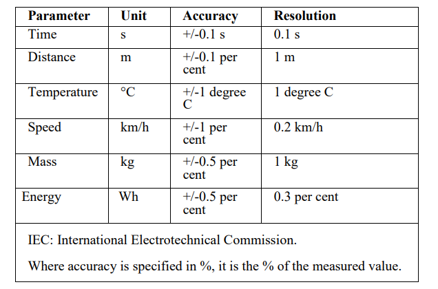
- Once the charge is finished, the cycle is measured with the chassis dynamometer, and the distance covered is calculated after the driving cycle.
- The electrical energy consumed is calculated by C=E/D where E – Energy in Wh, D – distance covered during the test, and C – distance covered.
– Test Interpretation:
– The energy consumption value is adopted by the test value and compared with the manufacturer’s denoted value. If it exceeds 4%, the test will be repeated in the same vehicle, and the two tests’ averages will be considered again. If the value once again exceeds the 4% criterion, the test will be repeated for a final time, and the average of the three tests will be considered. and If it goes beyond the test will fail
– and If the value or the average is less than 4%, the range denoted by the manufacturer will be considered the manufacturer’s test conditions.
CMVR Homologation conditions:
– For every vehicle, the homologation conditions are specified by CMVR (Center motor vehicle rules)
– The vehicle conditions are specified following the rules of 1989.
– According to this, the vehicles are specified as
- L1 – Two-wheelers without Gears and speed not exceeding 70km/hr.
- L2 – Two-wheelers with or without gears with maximum speed beyond 70km/hr
- M1 – Four-wheelers with less than 8 seats. (also with vehicle weight less than 3500 kgs),
- M2 – Four-wheelers with greater than 8 seats and gross vehicle weight of more than 3500 kgs)
- N1, N2 – Four-wheelers for cargo
AIS – 40 Measuring the Range of EV:
- The test sequence follows AIS039, and then instead of considering 4%, it’ll go up to 50km/hr or 85% of the marked maximum speed of the driving cycle or vehicle(for L1 vehicles alone), the vehicle will then decelerate to 5 km/hr by deactivating the accelerator control and then braked. If the vehicle doesn’t accelerate enough to achieve the speed of the test cycle, the accelerator control will be activated till the speed moves following the reference cycle.
- The distance measured “D” corresponds to the range of the electric vehicle.
AIS041 – Electric Motor characterization:
The auxiliaries that need to measure net power and a maximum of 30 minutes of the electric motor are shown in the figure below.
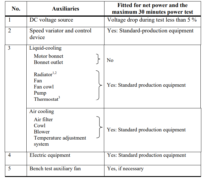
- The radiator, the fan, the fan cowl, the water pump, and the thermostat shall be located on the test bench in the same relative position as on the vehicle. The radiator, the fan, the fan cowl, the water pump, and the thermostat shall be located on the test bench in the same relative position as on the vehicle. The cooling-liquid circulation shall be activated by the motor liquid pump only. Cooling of the liquid may be produced either by the motor radiator or by an external circuit, provided that the pressure loss of this circuit and the pressure at the pump inlet remain substantially the same as those of the motor cooling system. The radiator shutter, if any, shall be in the open position. Where the fan, radiator, and fan cowl cannot conveniently be fitted for the bench test, the power absorbed by the fan when separately mounted in its correct position concerning the radiator and cowl (if used), shall be determined at the speed corresponding to the motor speeds used for measurement of the motor power either by calculation from standard characteristics or by practical tests. This power, corrected to the standard atmospheric conditions, should be deducted from the correct power. (reference AIS-041 Electric Power Train Vehicles – Measurement of Net Power and the Maximum 30 Minute Power, Pdf can be found here)
- Where a dis-connectable or progressive fan or blower is incorporated, the test should be carried out with the fan (or blower) disconnected or at maximum slip condition.
- The thermostat may be fixed in the fully open position
Auxiliaries to be removed:
- For the test, the auxiliaries removed are – Air compressors for brakes, the compressor for power steering and suspension systems, and the air conditioning system.
- If they’re unremovable, the power consumption for the above auxiliaries under no external loading conditions will be determined and added to the final condition.
- The supply voltage supplied by the vehicle manufacturer is used, and the DC electric motor with a maximum of 5% on time and current with less than 10s are added.
Chassis Dynamometer procedure;
- The consideration of the friction losses from the power and drivetrains and the corresponding auxiliaries is necessary while the other friction losses are removed. This is usually correlated by calibration of the dynamometer by coasting down.
- The power supply is considered by the REESS, which is calibrated as in AIS039.
Setting Procedure:
- The setting procedure is considered per the manufacturer’s guidelines with no alteration for that particular application.
Recording:
- Net power is considered by speed maximum at full controller setting.
- The torque and speed are recorded simultaneously.
- In a particular condition, the temperature at the motor outlet for a liquid-cooled motor must be maintained at ±5℃ of the thermostat, and for an air-cooled motor, it must be between +0/-20℃.
Accuracy:
- Torque – ±1%, the accuracy in the lower half is between 1/-2% of the measured torque
- Motor inlet temperature – ±2℃ and vehicle speed – ±1kmph.
Determining net power:
- The temperature for the test is 25±5℃ for a minimum of two hours before the test, and the test for net power will consist of running the motor at full power.
- Before beginning the test, the vehicle will run on the dynamometer and or the chassis at 80% of the maximum rated power.
- The minimum number of tests is 4 for the definition of the power curve through minimum and maximum speeds recommended by the manufacturer.
- For determining 30-minute power, the speed will be monitored at a specific range while running at more than 90% of the specified net power. The power range is at ±5% of the power value at the start of the test, and the maximum power is the average of the power within the 30-minute test.
Test Results:
- The net power and the 30-minute power shouldn’t be more than ±2% of the power specified by the manufacturer and not more than ±4% at other measurement points on the reference curve with a tolerance of ±1 kmph for vehicle speed and or ±2% of the motor speed as both power and speed were measured in the test.
Additional CMVR Rules:
Braking Rules:
- The manufacturer must attach the requirement of the appropriate braking system for the REESS test. The types of braking are
- Electric regenerative braking system – where the kinetic energy during deceleration is converted to electric energy using the vehicle drive motor(s).
- Regenerative braking control – The device that regulates the action of regenerative braking
- Regenerative braking category A – where the regenerative brake and the service brakes aren’t the same
- Category B – the service and the regenerative brakes are the same.
- Requirements of the regenerative braking system.
- For category A vehicles, the braking will activate either during acceleration control or neutral gear.
- As the discontinuation of the regenerative braking system is impossible, the service braking must actuate the regenerative braking system simultaneously, and the gear ratio must not affect the braking of the vehicle.
For Two-wheelers:
- If the brake control (either of the brakes or both) actuates regenerative braking, the performance of must is complied with and compiled per reference curve.
- IF there’s no actuation, the braking characteristics are considered without the usage of regenerative braking.
Additional Terminologies used:
- Active Driving possible mode: The minimum pressure on the accelerator pedal to make a vehicle move.
- Auxiliary battery: the battery unit where the reserve energy is for the auxiliary network supply
- Drive train: Specific parts of the powertrain, such as the traction motor, the appropriate electronic control, and the associate programs around it.
- Electrical Chassis: A set of conductive parts linked together with their potential is taken as the reference.
Reference Mass
- For two-wheelers – 75kg
- Three-wheeled vehicles L1, M1, and M2 (GVW) of up to 3500 kgs, the unladen or reference mass is at 150 kg
- M2 (above GVW of 3500 kgs) – an unladen mass of 75kgX50% seating capacity and the same as M2
- Unladen Mass – Mass of the vehicle is running without any load or passengers.

 AIS 039 – Energy consumption: